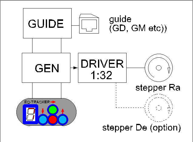
EQ Tracker is complex of several independent electronic modules connected phisicaly and logicaly on one mainboard. Main parts of EQ Tracker are: programable quartz generator, stepper driver
and guide module. Programable generator is heart of system and is described later. Stepper driver has default one channel for Ra ax with possibility of expantion
to second channel (De ax). Main advantage of this module is microstepping which can be set manually on the main bord in range 1:1 - 1:128. In using with platform default setting is 1:32. Guide module cooperate with programable generator and can be controled by TTL logic or non potential relay switch under GuideDog, GuideMaster, PH Guide, SBIG style or similar. Programable generator is adopted from original design called AstroPilot and has several modes described with digit 1 - 9 on display:
- mode 1 - mode manual (sideral speed)
- mode 2 - mode manual (speed = 2 x sideral speed)
- mode 3 - mode manual (speed = 10 x sideral speed)
- mode 4 - mode manual (speed = 20 x sideral speed)
- mode 5 - mode manual (speed = 100 x sideral speed)
- mode 6 - mode automatic (moon speed - little less than sideral)
- mode 7 - default mode, mode automatic with guide possibility (sideral speed)
- mode 8 - mode automatic (sun speed - little less then sideral)
- mode 9 - configuration mode (setting sideral speed)
Modes 1 and 7 are very similar but mode 7 allow guide. Default mode is 7 and appears always after power on. In using with platform interesting modes are 7 and 9. In mode 9 is possible change of sideral speed (used in mode default - 7) but it is only sometime necessary. Usually is enough to power on and forget about modes, settings and another regulations but in gude option maybe could be better to adjust speed more acurate in mode 9. Modes 1-5 (specially 4-5) can be usefull only for testing how platform works in acceleration.
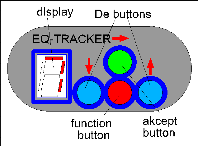
To manage modes in EQ Tracker two buttons and display are used. EQ Tracker has 4 buttons but two of them (gray/blue painted) working with second ax in 2 ax platform model and has meaning only in 2 ax guide mode. Modes can be changed by Function Button (FB red painted). To change mode push and hold FB and look at display where modes will rotate with rule:
7 -> 8 -> 9 -> 1 -> 2 -> 3 -> 4 -> 5 -> 6 -> 7 -> 8 -> 9 -> 1 -> ........and so on.
To choose, for example mode 4 (manual, 20 x sideral speed) wait until on the display will be digit 4 and release the FB (red). Digit 4 will start to blinking. To accept mode 4, press green Accept Button (AB). Engine will work with speed 20x faster than sideral. When FB (red) button will be presed against AB then process of choice will be continue. |
|
A little bit of theory - how it's works.
Stepper engine is driven by stepper driver controled by programable quartz generator. Quartz generator consist with 3 parts:
- base generator - usually 8MHz (8000000Hz)
- software divider
- hardware divider
Output frequency (fout) can be count by dividing source frequency (8MHz) by soft divider and hardware divider:
fout=fo/seq/n where: seq-soft divider, n-hardware divider.
By changing seq (sequency) and n, output frequency (fout) can be adopted to any condition.
Hardware divider means chip divider and n is set by shortener on the mainbord manualy.
Usually n is set default to 2 and don't need be changed.
Software divider called seq is controled by 2 buttons and 7 segment display. Software divider is always stored in memory so after restart is recalled. Software divider means sequency which setting proper configuration of divider. Sequence is 6 digit number and consist with 2 parts. First part is the first, left digit and second part is next 5 digit. First digit means rough step divider, next 5 digits mean precise divider. Summary divider is multiply of both parts. Rough divider can be setup with the following rules:
- 0 - means dividing by 2 (default setting enough for platform and most using)
- 1 - means dividing by 16
- 2 - means dividing by 64
- 4 - means dividing by 512
The rest of seguence means exactly secon divider. For example, if sequence is 026700 then first divider (digit 0) is 2 and second divider 26700 means exactly 26700 so efective divider is 2x26700=53400. This way, frequency after software divider, can be count as 8000000/2/53400. Output frequency depends also on hardware divider (usually 2) and fout can be count as 8000000/2/53400/2=37.453Hz. This frequency driving stepper motor through stepper driver.
Driving is stable, accurate and can be changed by software or/and hardware divider. Usually hardware divider is set at value 2 and can be left as is. |
|
Software divider (seq or sequency) is controlled by 7 segment display and 2 buttons. Sequency is directly responsible on sideral speed (modes 1 and 7). Sequency can be changed in mode 9. To change it just press and hold red, function button (FB) and wait until on display appears digit 9. Release FB - digit 9 will start to blinking. To accept mode 9 press green accept button (AB). You are on main level of configuration mode. Observe display and try write out sequence of digits which will appear on the display. Lets say that actual sequence is 026700. Sequence starting with display off. Next digits means sequence displayed in loop as follow:
display_off -> 0 -> 2 -> 6 -> 7 -> 0 -> 0 -> display_off -> 0 -> 2 -> 6 -> 7 -> 0 -> 0 -> display_off ..... ans so on. |
|
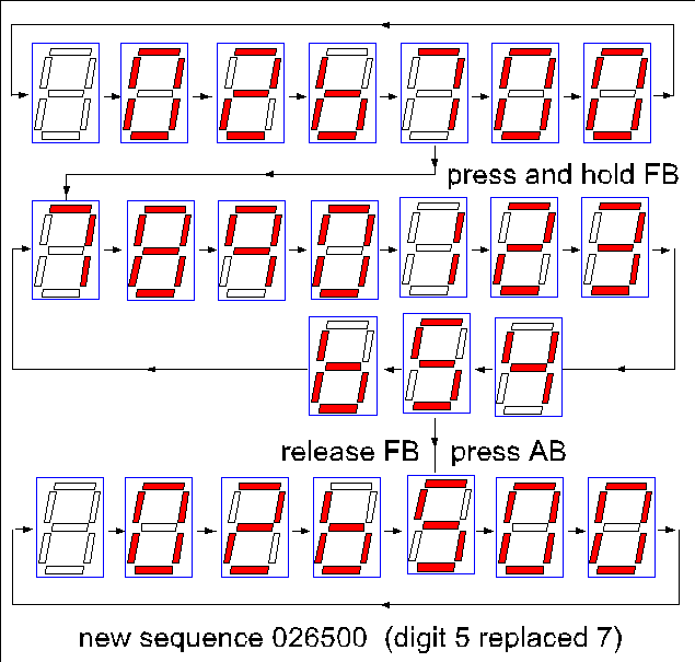
Assume that new sequence should be 026546 (how to check it?). On the begining digit 7 should be replaced by digit 5. Wait until on display appears digit 7 and hold and press FB (red). On the display digits will be display in loop:
7 -> 8 -> 9 -> 0 -> 1 -> 2 -> 3 -> 4 -> 5 -> 6 -> 7 -> 8 -> 9 ...... and so on.
Release FB when on the display appears digit 5. Digit 5 will be blinking. Using FB button means continue of choise digit but using AB button (green) means acceptation of selection. System return to main level of configuration mode and on the display sequence will be now with digit 7 replaced by 5 as follows:
display_off -> 0 -> 2 -> 6 -> 5 -> 0 -> 0 -> display_off -> 0 -> 2 -> 6 -> 5 -> 0 -> 0 -> display_off ..... and so on.
Next digit to change in sequence is zero on 5 position. Wait until digit 0 on fifth position appears on the display and hold and press button FB (red) as before and wait until on display will be digit 4. Release button FB (red) and accept digit 4 at this position with button AB (green). Now sequence is:
display_off -> 0 -> 2 -> 6 -> 5 -> 4 -> 0 -> display_off -> 0 -> 2 -> 6 -> 5 -> 4 -> 0 -> display_off ..... and so on
The last change should be done at last 0 position so use again FB button when on display will be last 0 in sequence and select digit 6. Accept it with AB button (green) and now sequence on display is:
display_off -> 0 -> 2 -> 6 -> 5 -> 0 -> 6 -> display_off -> 0 -> 2 -> 6 -> 5 -> 0 -> 6 -> display_off ..... and so on |
|
Now sequence is proper and can be stored in memory. To do it press and hold AB button (green) until
whole sequence will rewind on display and at the end on display appears two times digit 9. It means that sequence has been stored. Power off, wait 5-10 sec and power on. Now new sequence is working what can be tested in mode 9 (pres FB, wait until 9 on display and use FB). Until new sequence will be stored, sequence manipulation can be broken at any moment just with power off and all changes will be lost. Don't panic, if You lost in manipulation in mode 9 just power of and try again. |
|