back
back |
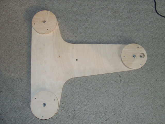
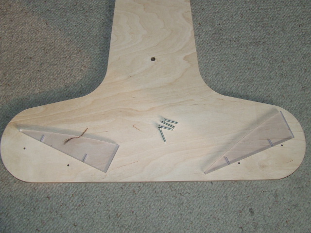
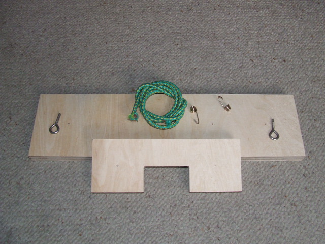
Step 1 - set of elementsMain elements are made from playwood #18mm. Rollers suppors and stepper supports as well runner are made from policarbon. All playwood and policarbon elements are prepared on CNC machines. All elements has construction holes made exactly in place so mounting is precise and easy. Set of details consists: bottom and top plates, legs and leg supports, roler suports, runners, rollers, stepper engine, driver and several screws and more detailed elements. Every element has it's own place in platform and no one is absent or spare ;-). |
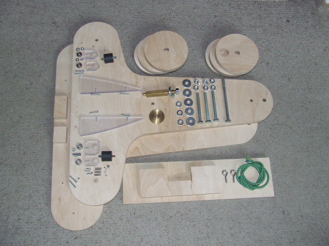 set of elements (without stepper and driver) |
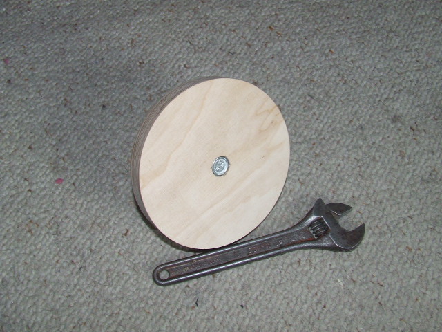
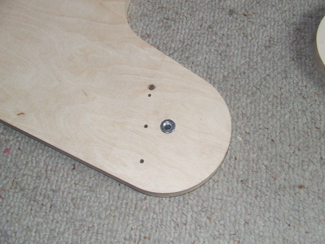
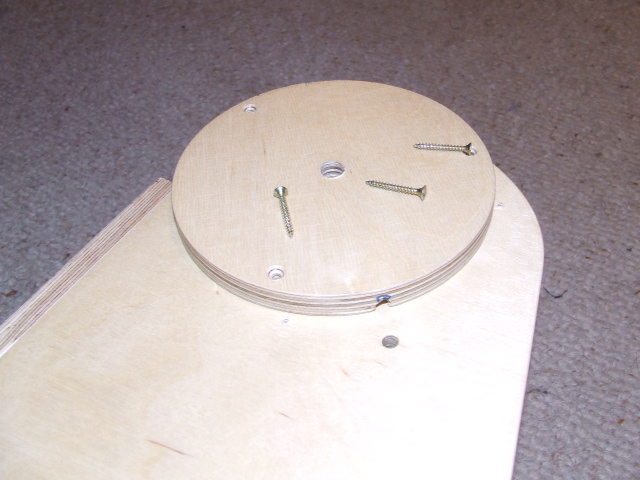
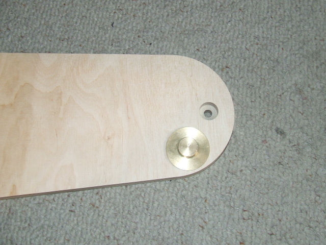
Step 2 - Preparing playwood elementsAll You need to mount equatorial platform is: hammer, screwdriver universal key or M10 key, sand paper (size 200-300), painting staff, transparent or coloured varnish. All palywood elements should be on start polish with sand paper and painted first time. When all elements be dry, polish it again with sand paper and clean off dust. Dry and cleaned elements should be painted second time. Perfectionists can repead polishing and painting third time ;-). Picture shows how to recognize top surface of bottom plate. This side has bigger whole for screw nut. |
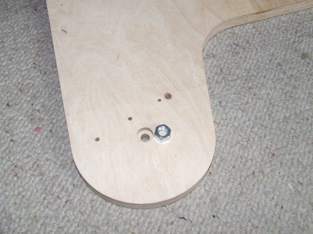 top side of bottom plate |
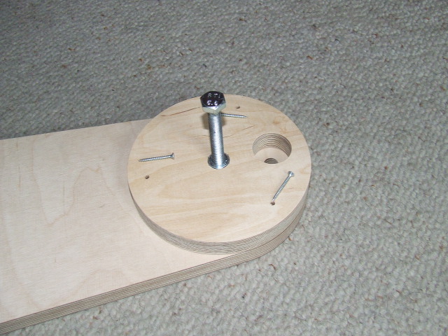
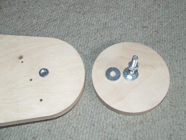
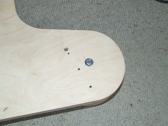
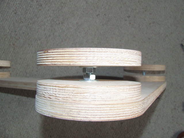
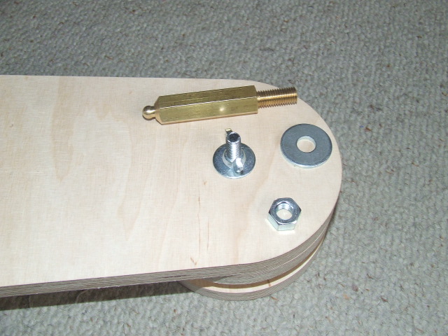
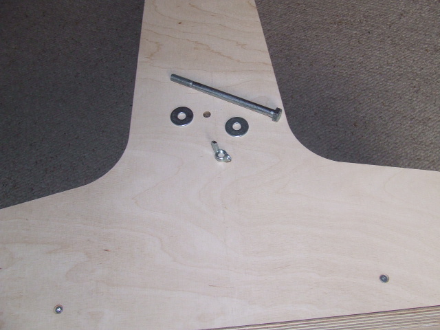
Step 3 - Mounting legs Platform standing on 3 playwood legs #18mm. Two of them are regulated and third leg, behind stepper, should be set once according to the local latitude. Every leg has playwood circle, M10 screw with nut and washer. To properly mount leg use universal or M10 key (key nr 17). Screw should be inserted into circle from bigger whole side and nut with washer from another side. Head of the screw should 'dive' in playwood. Additional elements of legs are butterfly nuts and washers which helps to setup legs on right place during platform regulation. |
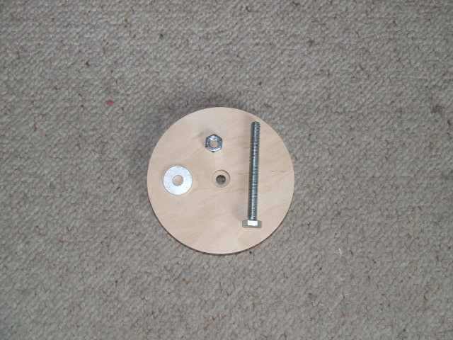 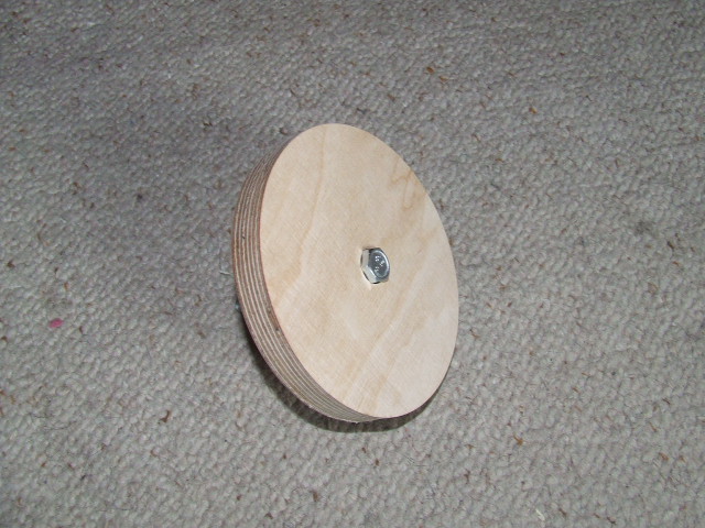 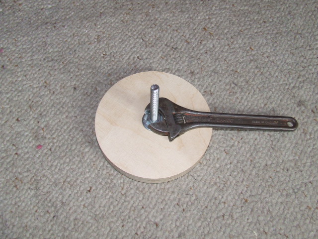  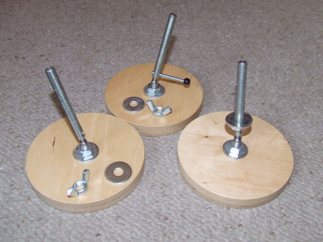 legs mounting |
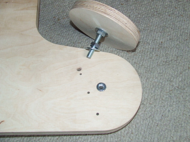
Step 4 - Mounting nuts in leg supportsLegs are fastened in bottom plate with supports (playwood #12mm) and butterfly nuts. Supports are mounted from bottom side of bottom plate. Nut M10 should be placed (inserted) into whole as described before in step 3. to do it use universal key, additional M10 nut and washer. Right leg support (under stepper engine side) has only M10 hole and nuts are mounted on both side of leg screw. This leg has always the same position. Support with big excentric hole is mounted on narrow side of bottom plate. |
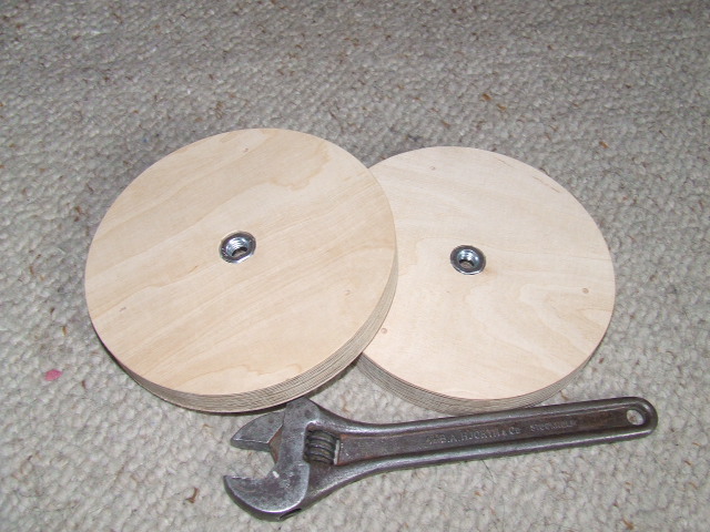  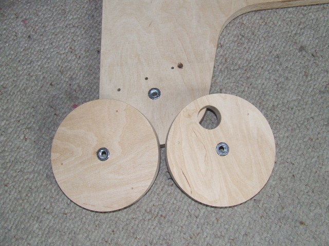 nut mounting in legs suports |
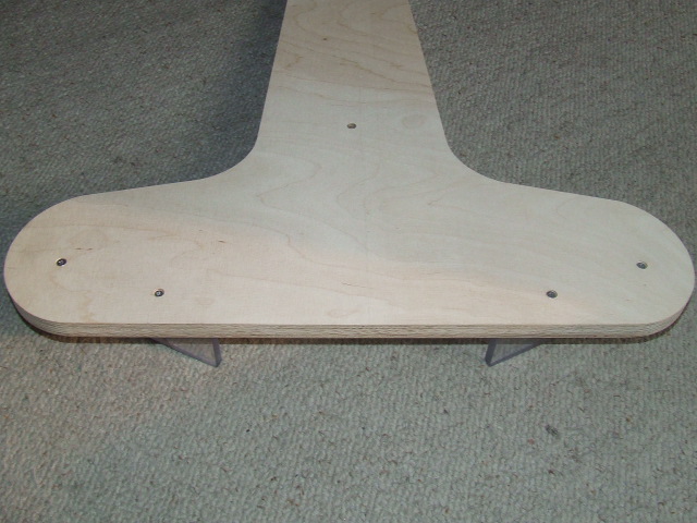
Step 5 - Mounting legs supports on bottom side of bottom plateOn the picture is showed support mounted on south side of platform. The excentric hole shoud be centered just equal to hole for south bearing pivot. To correct mount support use M10 screw inserted in both holes. Leg supports are fastened with three screws. Support behind stepper engine has special route for engine cable so should be fastened with cable holes in the line. |
 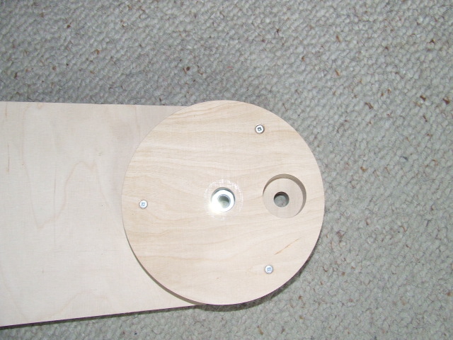   leg supports mounting |
Step 6 - Mounting right (non regulated) legRight leg should be fastened once acocording to the local altitude. It's help further setting platform to work. This leg is fastened with two nuts: one of them is mounted from top side as described in step 4 and second is mounted from bottom side with universal or M10 key and washer. This leg should be regulated only if place of working has altitude much different (>1 deg) than usually. |
    right leg mounting |
Step 7 - Mounting upper plateOn upper plate should be mounted runners and one point bearing nest. Bottom side of this plate can be recognized by bigger hole dedicated for nest. Nest should be pushed in hole with hammer. Hit the nest with hammer using piece of wood between nest and hammer. Runners are mounted with two screws. Wider parts of runners should be oriented to each other. |
   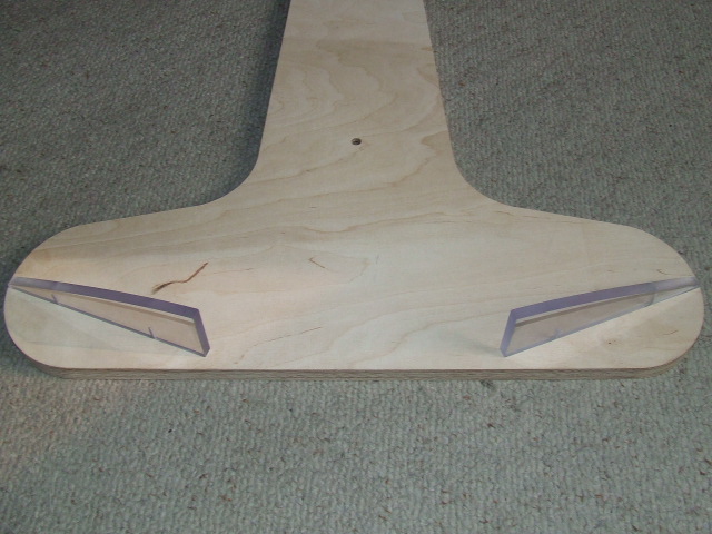  top plate mounting |
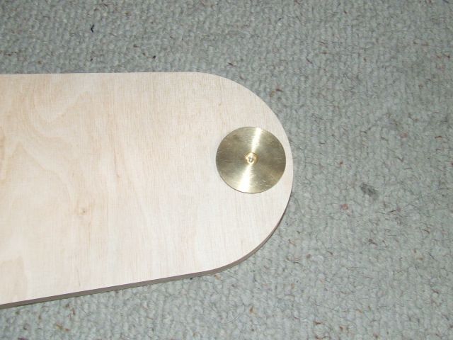
Step 8 - Mounting pivot of south bearingPivot should be mounted with M10 nut and two washers from each side. |
 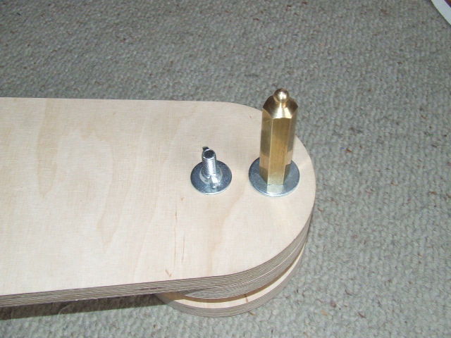 one point bearing pivot mounting |
Step 9 - Passive roller mountingPassive roller (left side of bottom plate) is delivered as already assembled set of parts with bearings and polycarbon supports. Passive roller set is mounted with two screws from bottom side of bottom plate. To do it, first should be dissasembled leg support described in step 5. Leg support should be mounted again on place after passive roller mounting. |
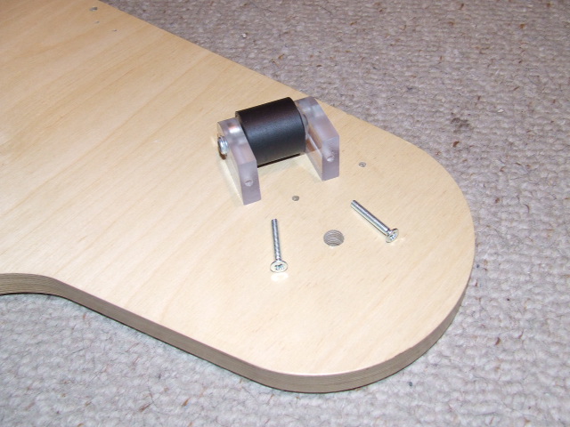 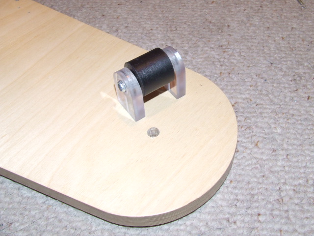 passive roller mounting |
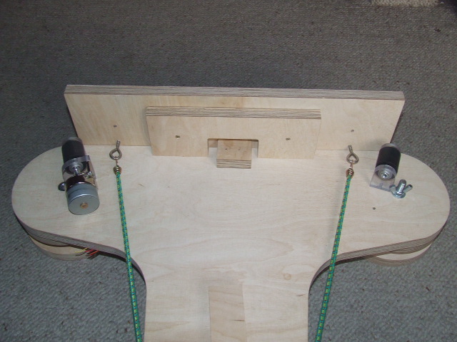
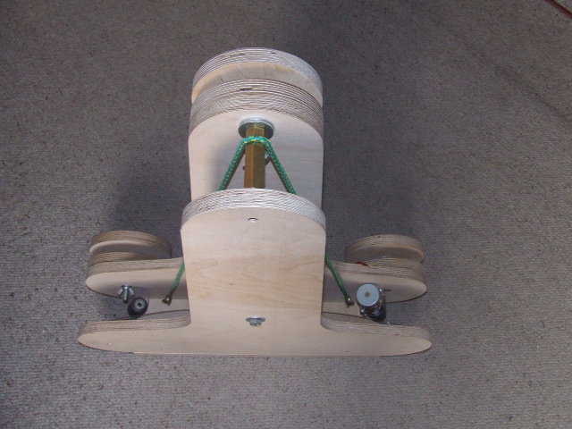
Step 10 - Active roller mountingActive roller (right side of bottom plate) is delivered as already assembled set of parts with bearings, polycarbon supports and stepper motor. Active roller set is mounted similar to the passive roller with two screws from bottom side of plate. Similar to step 9, in this step leg support should be first disasembled and assembled again. The only difference is stepper motor engine cable which must be passed throught hole under engine on bottom side of plate. |
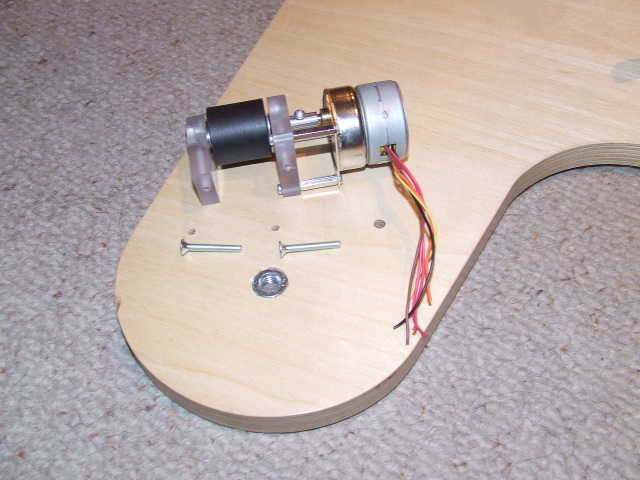 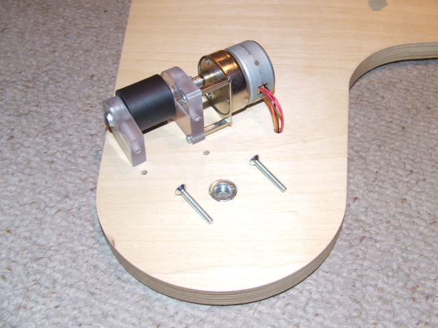 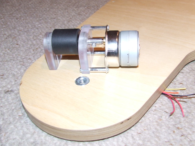   active roller mounting |
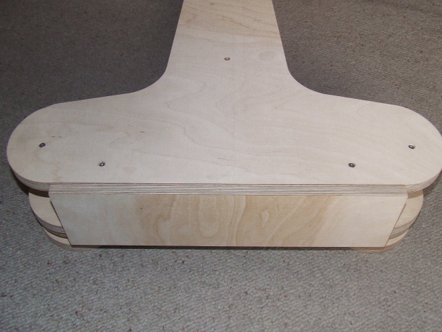
Step 11 - Run limiter mountingRun limiter consist of two playwood elements and switch with cable. Switch is already assembled to the bottom part of limiter. First insert switch cable into hole in bottom plate. Next, cover limiter with top part and finally connect together with bottom plate wih 2 screws. Switch activate sound buzzer whwn platform will reach end of track. |
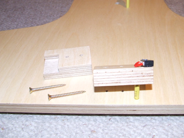 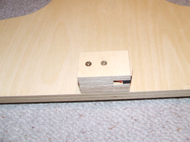 run limiter mounting |
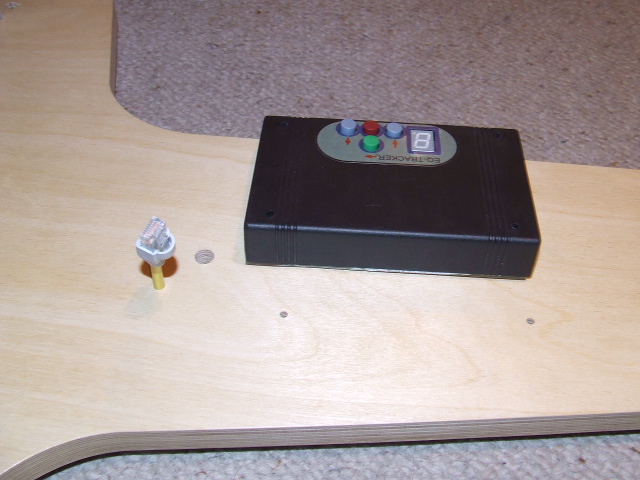
Step 12 - Electric cable mountingAll electrical cables (stepper engine cable, switch cable and driver cable are already prepared with sockets. Every single cable has unique coloured end. All You need to do is connect all the same coloured cables together. At the start of this step insert in hole driver cable (ended with 8 pin RJ45 connector) from top side of plate as described in step 10. One of the connected elements is buzzer activated when platform will reach end of track. Cable connection is covered with plastic cap and screw. Watch out to cover it properly avoid collision tap with cables and sockets. The last task is fastening cables to the plate surface with flop fasteners and hammer. Align cables achieve vertical and horizontal directions of cables. |
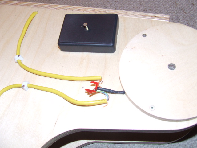 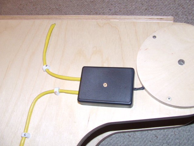 electric cable mounting |
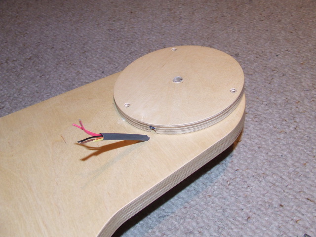
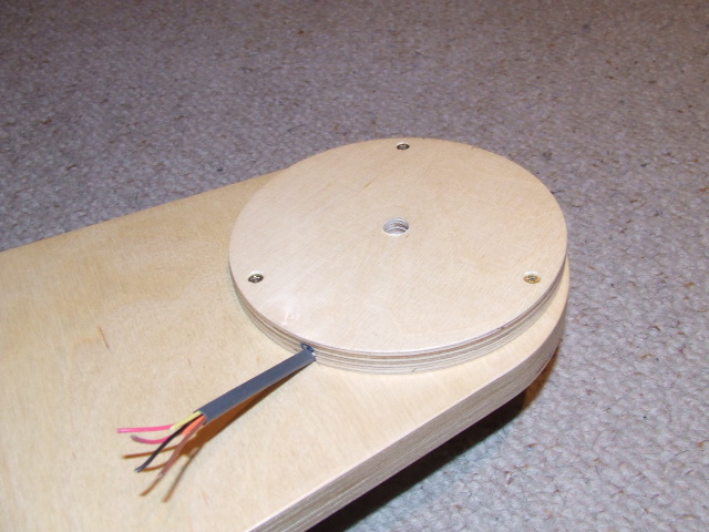
Step 13 - Stepper driver mountingStepper driver, called EQ Tracker, is delivered as ready to mount element. First connect driver cable to the Ra ax socket in driver. Driver is assembled on top side of bottom plate with 4 screws from bottom side. Driver has battery cable and optional connector which can be used with additional power suply. |
 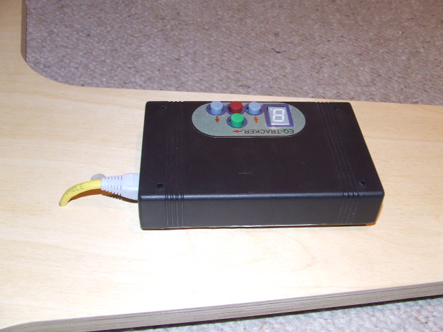 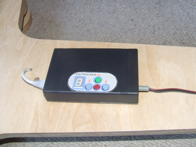 stepper driver mounting |
Step 14 - Transport shield mountingTransport shield allow to carying equipment during transport as well when platform is 'out of duty', Transport shield consist front cover, flexible rubber and central screw. Front cover consist with two playwood plates and two circle ended screws. First connect playwood plates with small screws. Next, mount two circle head screws. Flexible rubber is ended with small hooks. To set transport shield first place front cover on place, next connect rubber with circle ended screws and strech it over south bearing pivot. Place top plate on place and connect all together with M10 screw and two washers and butterfly nut. Now platform is ready to transport or can wait for the next clear sky. |
 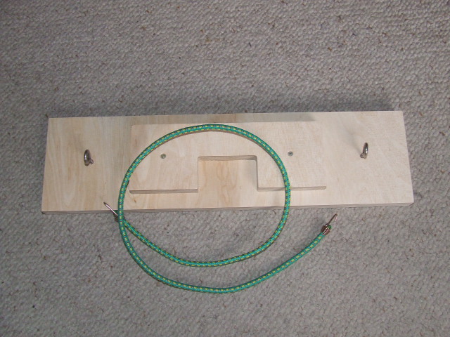     transport shield mounting |
Step 15 - Just enjoy of Your workIf You have arrived here You are probably ready to start using platform. First direct platform along north-south line, put the telescope on platform, power platform on and enjoy of stable sky beauty with any desired magnification. |
 platform in run |
back |